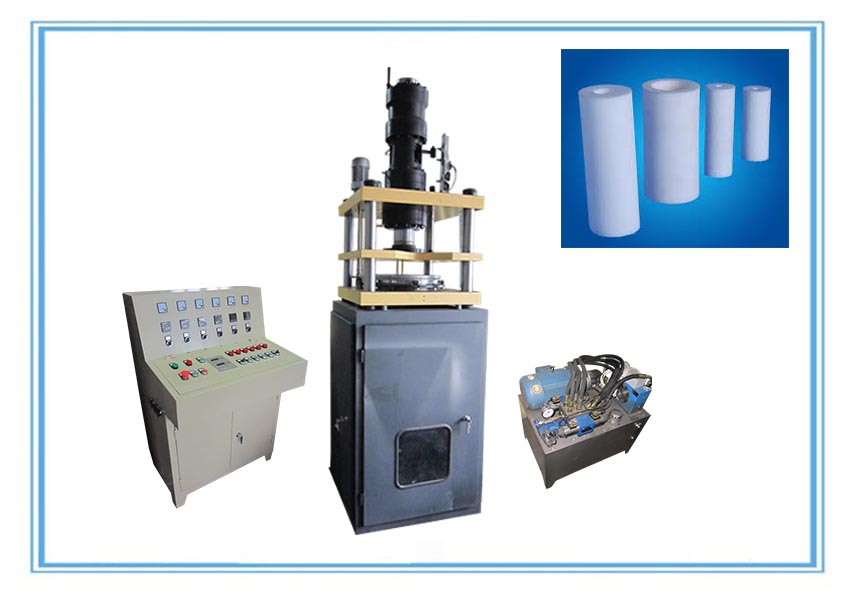
Injection moulding is a two step cyclical process: (a) melt generation by a rotating screw, and (b) Žfilling of the mouldwith molten polymer by the forward ramming of the screw (called a reciprocating screw), followed by a very short packing stage necessary to pack more polymer in the mould to offset the shrinkage after cooling and solidiŽ cation. The material is held in the mould under high pressure until it has solidiŽfied sufŽ ciently to allow ejection.
 Polymer injection molding has certain similarities to the die casting process of metals, in which molten metal is forced under high pressure into a steel mould or die. The metal, as the polymer, is pressed into all the crevices of the mould and the pressure is held while the metal freezes.
In polymer injection moulding, the melt path into the mould starts with a sprue, and splits off into individual runners each feeding one of the multiplicity of mould cavities through a gate. Moulds can contain over 100 cavities, each producing a part per injection cycle. Cycle times range from a few secondsto over a minute. Numerous productsranging from boat hulls, lawn chairs and appliance housings to radio knobs and bottle caps are injection moulded. Very high shear rates arise in injection moulding operations (usually up to 104 s21 ) and, to limit temperature increases from viscous heating and also to facilitate easy filling, low viscosity thermoplastic polymer grades are used.
Injection moulding machines are rated by the size of their clamping systems, which are hydraulic, electrical or mechanical toggle systems used to hold the mould closed with sufŽficient force to resist the injection pressure. Machines available usually range from 5 tons for a shot of ~10 g to 5000 tons for shots of more than 50 kg (shot is the total amount of material pumped into the mould in a cycle, including that in the sprue, runners and cavities). Some bigger machines have also been built for the production of very large moulded products. Micromoulding, in which the shot size is below 1 g, is recently finding increased use in biomedical and nanotechnological applications.
Simulation software is used extensively in the design of injection moulds, because of the ability of the Hele – Shaw flow approximation to describe reasonably well the mould Žfilling process. More recently, however, three-dimensional models of flow simulation have come into use. Economics also provide an incentive for the use of software, as moulds can be extremely expensive to make, so minimising trial and error procedures on the factory oor is desirable. The software is used to design the part cavities, to balance runners, to visualise the filling process, and to predict orientation, shrinkage, warpage and weld lines in the product.
Among the challenging problems faced in computer simulation is the prediction of shrinkage and warpage. Shrinkage is the difference in dimensions between the mould and the cooled moulded part. The main cause is the density increase which occurs as the melt freezes. Crystalline poly- mers such as polyamide (PA, nylon), high density PE, PET and PP give the worst problems, with shrinkages of 1 – 4%. Amorphous polymers such as PS, PMMA and PC have fewer problems, shrinking only 0.3 – 0.7%. Warpage is caused by the density changes mentioned above, and orientation imparted to the part during cavity Žfilling and packing, decidedly in a non-uniform manner.
Gas assist injection moulding involves the injection of nitrogen with the plastic, which creates a hollow void in the moulded part.This allows large parts to be moulded with lower clamp tonnage and signiŽ cant material savings. This innovative process started in the 1980s and its use is rapidly growing.
The process of reaction injection moulding (RIM) involves the injection of low viscosity liquids, which become reactive when mixed and polymerise within the mould.The advantage of this processis that the pressures are low owing to the low viscosities. A disadvantage is the requirement to handle highly toxic substances. Although initial projections called for signiŽficant growth in RIM, this did not materialise. In fact, some manufacturers of automotive parts by RIM have switched to conventional injection moulding.
Source:http://ptfe-machinery.com/injection-moulding-process-injection-moulding-machines/
Source:http://ptfe-machinery.com/injection-moulding-process-injection-moulding-machines/
No comments:
Post a Comment