Thursday, March 30, 2017

Synthetic String Plant

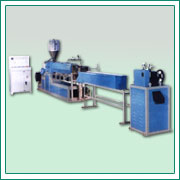
Synthetic string (sutli) plant is the plastic extrusion plant where plastic string is extruded. Especially in the packaging industry plastic string are used extensively.Plastic sutli plants with high output and less energy consumption are required. There are wide range of synthetic string plants that are used to manufacture string using PP synthetic jute, polymides,etc. Machine made from special Nitro alloy steel gives long and trouble free operations. 

Due to environment, economical and other issues strings made from natural materials like coconut fiber and cat gut is being largely replaced by synthetic string. The synthetic string machine manufacture are constantly trying to develop synthetic string plants that will enable manufacturing synthetic strings that can suitably replace the one's manufactured from natural materials. In addition, innovative range of machines are developed for new and varied applications. At the present stage of technology, synthetic strings that are manufactured meet virtually all requirements in regards to wear resistance and constancy of tension in all climates. 


Process 
Different types of synthetic string plants are available that help in manufacturing different types of twisted string, untwisted synthetic string, etc. Some techniques used to manufacture synthetic string are elucidated here:

Untwisted synthetic resin string: In one method of manufacturing, melted polymer is passed through rolled portions, with each roll moving inward towards each other, The opposite edges of the strip of thermoplastic resin film is stretched longitudinally.
Twisted strings: Synthetic film or split yarn is obtained by slitting a stretched synthetic resin film. Stretched synthetic resin is then mechanically twisted. 

Quality of the machine

The synthetic string plant should have excellent shock-absorbing properties, bulkiness, uniformity, tensile strength and binding ability so as to be able to manufacture strings which are lightweight, flexible and free of fluffiness. Other qualities that are essential for the machine are:
  • High productivity
  • Durability
  • Compact design
  • Customer friendly
  • High speed strappin

Application

Plastic string also know as sutli is used extensively for packaging things both at homes and in industries. Plastic string are reliable and perfect substitute for jute sutli and twisted rope making. Synthetic resin strings are also used for automatic packaging or binding machines, agricultural binders, hay balers and also for handicraft knitted articles. Plastic strings are also used in ball rackets and musical instruments.

Wednesday, March 29, 2017

Hydrostatic Extrusion Advantages

Hydrostatic extrusion is a process in which the billet is completely circumscribed by a pressurized liquid in all the cases, with the exception being the case where billet is in the contact with die. This process can be carried out in many ways including warm, cold or hot but due to the stability of the used fluid, the temperature is limited. Hydrostatic extrusion has to be carried out in a completely sealed cylinder for containing the hydrostatic medium. The fluid may be pressurized in following two ways:
  1. Constant-Rate Extrusion: A ram or plunger is used for pressurizing the fluid in the container
  2. Constant-Pressure Extrusion: A pump with a pressure intensifier is used for pressurizing the fluid, which is then pumped into the container
Advantages of Hydrostatic Extrusion
  • No friction amidst the container and billet. This minimizes the force requirements, allowing higher reduction ratios, faster speeds, & lower billet temperatures.
  • Friction of the die can be largely reduced by a film of pressurized lubricant amidst the die surface and deforming metal.
  • On applying high pressures, the ductility of material increases.
  • Even flow of material.
  • Large billets & large cross-sections are extruded.
  • Uniform hydrostatic pressure inside the container eliminates the requirement of billets being straightened and extrusion of coiled wire.
  • No billet residue is left on the walls of container.
Disadvantages of Hydrostatic Extrusion

The billets have to be prepared by tapering one end so that it matches the die entry angle. This is essential for forming a seal at the starting of the cycle. Generally, the complete billet is required to be machined for the removal of surface defects.
It can be difficult to contain the fluid, under the effects of high pressures (up to 2 GPa, or 290 ksi). 

Limitations of Hydrostatic Extrusion 

There are a number of limitations in the hydrostatic extrusion, especially when a large volume of fluid is used in comparison with the billet volume, which is to be extruded. These limitations are as follows:
  • Increased handling for the injection and removal of the fluid for every extrusion cycle
  • Decreased control of speed of the billet & stopping because of potential stick-slip and enormous stored energy in the compressed fluid
  • Decreased process efficiency in terms of billet-to-container volume ratio
  • Enhanced complications, when extrusion is done at elevated temperatures
Solutions To These Limitations 

The problems related to the billet speed as well as stopping control can be minimized with the use of viscous dampers and also with the improvement in lubrication at the billet / die interface. There is another approach to minimize all the above mentioned problems, which is to maintain the amount of pressurizing fluid to an absolute minimum, as in the case of Hydrafilm process. 

Tuesday, March 28, 2017

Blown Film Extrusion Materials Used & Process

Blown Film Extrusion is an established process which is sued to manufacture a wide range of commodity & specialized plastic films for the packaging industry. Also known as Film Blowing Process, this extrusion process generally comprises extrusion of molten thermoplastic tube and its constant inflation to severaltimes of its initial diameter. This forms a thin, tubular product which may be used directly, or indirectly by slitting it to create a flat film.

Materials Used

In the process of Blown Film Extrusion, the common resins that are used are Polyethylenes (LDPE, HDPE and LLDPE). Though, various other materials can also be used in this process, as a blend with resins or even as single layers in the multi-layer film structure. Some of these materials are PP, PP, and EVOH. In few instances when these materials are not able to gel together, then a multi-layer film might get de-laminate. Hence, to overcome this issue, various tiny layers of special adhesive resins are used purposefully in between. These tiny layers are called “tie layers”.

Process of Blown Film Extrusion

The extrusion of plastic melt is done via an annular slit die, generally vertically, for the formation of a thin walled tube. The introduction of air takes place through a hole present in the die's center for blowing up the tube just like a balloon. The cooling of the hot film is done by the high-speed air ring that blows onto it. This air ring is mounted on the top of die. Then following procedures take place:


  • The tube of the film continues its movement upwards (constantly colling) till is is passed via nip rolls. Here, the tube is flattened for the creation of “lay-flat” tube of film. Also known as collapsed tube, this lay-flat tube goes back to the extrusion tower via rollers.
  • On the higher output lines, exchange of air (which is available in the bubble) takes place. This is called IBS (Internal Bubble Cooling).
  • Then the lay-flat film is kept as it is or its edges are slit off for producing 2 flat film sheets & wound up onto the reels. If kept as it is, the film's tube is created into bags by the process of sealing all across the film's width along with cutting or perforating. This process is carried out at a later stage or in line with the process of blown film.
Blown Film Extrusion

Monday, March 27, 2017

Applications in plastics processing machinery

Extruders

Specific AC and DC motor and drive solutions can be applied dependent on the type of end plastic product being produced as well as the type and size of the extruder. Motor types typically used include AC induction (enclosed or laminated frame designs), DC, servo or permanent magnet.

Variable speed drives are used for precise motor control and increased energy efficiency, as well as for environmental and cost reasons. Drives also provide dynamic torque limit for protection of the extrusion screw without speed or position feedback devices, resulting in lower initial investment and installation costs and higher operational reliabilit.

Downstream machinery

Various types of downstream machinery may be present to facilitate necessary cooling, take-off and/or other discrete handling of the extruded material, such as cut-to-length, slitting, stacking, coiling, etc. These are in general typical drive applications requiring drive performance characteristics ranging from speed or torque regulation to simple motor control.

Melt pump

The melt pump is fed by a speed-regulated, pressure-controlled extruder which provides precise control of the molten plastic output flow, optimizing the consistency of the flow delivery rate.

Film proccessing

Precise tension control is vital for plastic film processing. The superior speed regulation of ABB drives maintains the tension within the established limits and the fast, accurate drive-to-drive line speed communication provides precise synchronization of take-off roll sets.

Winder

Film must be wound under constant tension, requiring torque regulation of the winder motor, which must continually adapt to ever-changing roll diameters. This can be achieved either by using an ABB drive with winder software or integrating a separate PLC into the control system.

Wednesday, March 22, 2017

Injection molding machines operation

An Injection molding machine, also known as an injection press, is a machine for manufacturing plastic products by the injection molding process. It consists of two main parts, an injection unit and a clamping unit.

molding machines


Injection molding machines can fasten the molds in either a horizontal or vertical position. The majority of machines are horizontally oriented, but vertical machines are used in some niche applications such as insert molding, allowing the machine to take advantage of gravity. Some vertical machines also don't require the mold to be fastened. There are many ways to fasten the tools to the platens, the most common being manual clamps (both halves are bolted to the platens); however hydraulic clamps (chocks are used to hold the tool in place) and magnetic clamps are also used. The magnetic and hydraulic clamps are used where fast tool changes are required.

The person designing the mold chooses whether the mold uses a cold runner system or a hot runner system to carry the plastic from the injection unit to the cavities. A cold runner is a simple channel carved into the mold. The plastic that fills the cold runner cools as the part cools and is then ejected with the part as a sprue. A hot runner system is more complicated, often using cartridge heaters to keep the plastic in the runners hot as the part cools. After the part is ejected, the plastic remaining in a hot runner is injected into the next part.

Sunday, March 19, 2017

What is injection moulding and how does injection moulding work?


Injection moulding along with extrusion ranks as one of the prime processes for producing plastic articles. It is a fast process and is used to produce large numbers of identical items from high precision engineering components to disposable consumer goods.

Most thermoplastics can be processed by injection moulding; the most common materials used include:

  • Acrylonitrile-Butadiene-Styrene ABS
  • Nylon PA
  • Polycarbonate PC
  • Polypropylene PP

Injection mouldings count for a significant proportion of all plastics products from micro parts to large components such as car bumpers and wheelie bins. Virtually all sectors of manufacturing use injection moulded parts. The flexibility in size and shape possible through use of this process has consistently extended the boundaries of design in plastics and enabled significant replacement of traditional materials thanks to light weight and design freedom.

How Does Injection Moulding Work?

Material granules for the part is fed via a hopper into a heated barrel, melted using heater bands and the frictional action of a reciprocating screw barrel. The plastic is then injection through a nozzle into a mould cavity where it cools and hardens to the configuration of the cavity. The mould tool is mounted on a moveable platen – when the part has solidified, the platen opens and the part is ejected out using ejector pins.

After a product is designed, usually by an industrial designer or an engineer, moulds are made by a mould maker (or toolmaker) from metal, usually either steel or aluminum, and precision-machined to form the features of the desired part..

Parts to be injection moulded must be very carefully designed to facilitate the moulding process; the material used for the part, the desired shape and features of the part, the material of the mould, and the properties of the moulding machine must all be taken into account. The versatility of injection moulding is facilitated by this breadth of design considerations and possibilities.

More Details: Plastic Molding Machine

Saturday, March 18, 2017

Nylon and PTFE Filters Differences

Nylon membranes for filtration using syringe filter devices and which membrane can be used with different solutions and or sovlents.
PTFE as a membrane for syringe filters is considered to be more "chemically resistant" and Nylon to be the most "extractable free" for HPLC or dissolution testing. The simple explanation of the differences is that chemical resistance is defined as the durability of the membrane to withstand some harsh solvents (normally not used in HPLC or dissolution testing).
The PTFE membranes still have extractables that usually dissipate or become undetectable after the first 2-3 mls of filtrate are discarded but these membranes can have extractables even after the first 2-3ml (which will vary from supplier to supplier based on the quality of PTFE used). It should be noted that PTFE is hydrophobic by nature so most water based solutions have a hard time penetrating the membrane and require excessive hand pressure to use. This back pressure can be circumvented by "pre-wetting" the membrane with methanol with will allow aqueous based solutions to be filtered.
Some filter manufacturers will use surfactants in the PTFE membrane to make them more water compatible. If eluting surfactants are not of concern, this technology may work well.
Some solvents or solutions are not recommended for use with Nylon membranes as they may "swell" the membrane and or make them weak in that the membrane may disintegrate or simply burst allowing non filtered solution to pass through. However, for other more compatible solutions (most HPLC solvents and solutions) Nylon will provide the most "extractable free" membrane available and is hydrophilic which makes it good for use with water based solutions. Many organic solvents are very compatible with nylon.
Chlorinated solvents, strong acids and strong bases should be avoided when using Nylon membranes.

Friday, March 17, 2017

Porous PTFE Plastic Polymer


Polytetrafluoroethylene (PTFE) is a versatile polymer used in a broad range of medical, industrial, and high technology applications. Porous PTFE is inert, making it unreactive to most chemicals, and, it can work in high processing and operating temperature environments (500°F / 260°C continuous).

Porex porous PTFE offers excellent thermal, electrical, mechanical, and chemical properties as well as superior control over pore size, permeability, water entry pressure, and thickness. PTFE is an ideal choice for a wide variety of demanding applications requiring one or a combination of these exceptional properties.

PTFE MANUFACTURING STANDARDS

PTFE materials are manufactured in Class 100k clean rooms under ISO 9001:2008 quality standards. They are available in a variety of formats including rolls, sheets, die cut, and rotary cut parts and also with adhesive backings.

KEY BENEFITS

  • chemically inert
  • thermally resistant (500°F / 260°C continuous use)
  • compatible with ultrasonic/thermal welding and inset molding
  • hydrophobic and oleophobic
  • omni-directional flow
  • high tensile strength
  • steam and EtO (ethylene oxide) sterilizable
  • natural white or black color
  • UL 94 V-0 @ 0.1mm and 5VA @ 0.75mm
  • UL 746C f1 rating (outdoor weatherability)
  • low dielectric constant (to 1.43)
  • diffuse reflectivity up to 98%
  • used in medical devices


Thursday, March 16, 2017

About PTFE's Physical Properties

The structure of PTFE molecules

PTFE, poly(tetrafluoroethene), is made by polymerising lots of tetrafluoroethene molecules.
PTFE's Physical Properties
 
This simple diagram for PTFE doesn't show the 3-dimensional structure of the molecule. In the simpler molecule poly(ethene) the carbon backbone of the molecule just has hydrogen atoms attached to it, and the chain is very flexible - it definitely isn't a straight molecule.

However, in PTFE, the fluorine atoms in one CF2 group are big enough to interfere with those on the neighbouring groups. You need to remember that each fluorine atom will have 3 lone pairs sticking out from it.

The effect of this is to inhibit rotation about the carbon-carbon single bonds. The fluorine atoms will tend to line up so that they are as far apart as possible from neighbouring fluorines. Rotation will tend to involve a clash of lone pairs between fluorines on adjacent carbon atoms - and this makes rotation energetically unfavourable.

The repulsions lock the molecules into a rod-like shape with the fluorines arranged into very gentle spirals - a helical arrangement of the fluorines around the carbon backbone. The rods will then tend to pack together a bit like long thin pencils in a box.

This closely touching arrangement has an important effect on the intermolecular forces as you will see.

Intermolecular forces and the melting point of PTFE

The melting point of PTFE is quoted as 327°C. That's quite high for a polymer of this sort - so there must be sizeable van der Waals forces between the molecules.

But . . . several web sites talk about PTFE having very weak van der Waals forces. If it had very weak van der Waals forces, it would be a gas - not a fairly high melting point solid. So we have a problem here!


Why do people claim the van der Waals forces in PTFE are weak?

van der Waals dispersion forces are caused by temporary fluctuating dipoles set up as electrons in the molecules move around. Since PTFE molecules are large, you would expect the dispersion forces to be large as well, because there are a lot of electrons which can move.

It is generally the case that the bigger the molecule, the greater the dispersion forces.

However, there is a problem with PTFE. Fluorine is so electronegative that it tends to hold the electrons in the carbon-fluorine bonds closely to itself - so closely that the electrons are prevented from moving as much as you would expect. We describe the carbon-fluorine bonds as not being very polarisable.

van der Waals forces also include dipole-dipole interactions. But in PTFE each molecule is sheathed in a layer of slightly negative fluorine atoms. The only interactions possible between molecules in this case are repulsions!

So the dispersion forces are weaker than you might expect, and dipole-dipole interactions are going to tend to cause repulsion. It is no wonder that people claim that van der Waals forces are weak in PTFE. You don't actually get repulsion because the effect of the dispersion forces outweighs that of the dipole-dipole interactions, but the net effect is that the van der Waals forces will tend to be weak.

And yet PTFE has a high melting point, and so the forces holding the molecules together must be strong.


How can PTFE have a high melting point?

PTFE is very crystalline in the sense that there are large areas where the molecules are lying in a very regular arrangement. Remember that PTFE molecules can be thought of as long thin rods. These rods will pack very closely together.

That means that although PTFE molecules can't generate really big temporary dipoles, the dipoles that are produced can be used extremely effectively.


So are the van der Waals forces in PTFE weak or strong?

I think you could argue it both ways! If you had PTFE chains arranged in such a way that the chains didn't have much close contact, then the forces between them would be weak, and the melting point would be low.

But in the real world, the molecules are closely touching. The van der Waals forces may not be as strong as they could be, but the structure of the PTFE means that they are felt to the maximum effect, producing overall strong intermolecular bonding and a high melting point.


Non-stick properties and friction

Virtually every site that I have looked at treats the relative lack of friction of PTFE and its non-stick properties as if they were the same effect. I don't think that's true.

The non-stick properties

This is about why things like water and oil don't stick to the surface of PTFE, and why you can fry an egg in a PTFE-coated pan without lots of it ending up stuck to the pan.

You need to consider what forces might hold other molecules to the PTFE surface. Possibilities might include some sort of chemical bonding, van der Waals forces or hydrogen bonds.

Chemical bonding

Carbon-fluorine bonds are very strong, and there is no way that any other molecule could get at the carbon chain to enable any sort of substitution reaction to take place. No sort of chemical bonding could take place.

van der Waals forces

We've seen that the van der Waals forces in PTFE aren't very strong, and only work to give PTFE a high melting point because the molecules lie so close together and there is very effective contact between them.

But it is different for other molecules approaching the surface of the PTFE. A relatively small molecule (like a water or an oil molecule) will only have a small amount of contact with the surface, and will only produce a small amount of van der Waals attraction.

A large molecule (like a protein, for example) isn't going to be rod-like and so, again, there isn't going to be enough effective contact between it and the surface to overcome the low tendency of the PTFE to polarise.

Either way, van der Waals forces between the PTFE surface and whatever is around it are going to be small and ineffective.

Hydrogen bonds

The PTFE molecules on its surface are completely encased in fluorine atoms. Those fluorine atoms are very electronegative and so will all carry some degree of negative charge. Each fluorine also has three lone pairs of electrons sticking out.

Those are exactly the conditions needed for hydrogen bonding to be possible between lone pairs on the fluorines and hydrogen atoms in water for example. But it clearly doesn't happen - otherwise there would be strong attractions between PTFE molecules and water molecules and water would stick to the PTFE.

In November 2013, an Iranian PhD student pointed out to me a 1997 paper by Dunitz and Taylor with a title "Organic Fluorine Hardly Ever Accepts Hydrogen Bonds". If you are interested, you can find it from this site if you have the right access.

They found that only a tiny number of compounds containing C-F bonds would form hydrogen bonds, whereas compounds like HF or the F- ion formed strong hydrogen bonds.

What they didn't come up with, however, was any definite explanation for this, although they suggested that a possible explanation could lie in the fact that the fluorine atom holds its electrons very tightly in towards the nucleus, and as a result the C-F bond isn't very polarisable. The electrons won't move sufficiently towards a hydrogen from water (or anything similar) in order for a hydrogen bond to form.

Personally, I have a problem seeing why that is different from the situation in H-F or a fluoride ion, both of which can form hydrogen bonds with water.

And their final sentence said:

"At the same time, it has to be admitted that, in spite of the vast amount of work on hydrogen bonding over the years, the chemical factors influencing the strength of hydrogen bonds (especially factors influencing H-bonding acceptor ability) are still not completely understood."

Summary

There are no available methods for other molecules to attach themselves successfully to the surface of the PTFE, and so it is has a non-stick surface.


The low friction

PTFE has a very low coefficient of friction. What this means is that if you have a surface coated with PTFE, other things will slide on it very easily.

What follows is just a quick summary of what is happening. This comes from a 1992 paper called Friction and wear of PTFE - a review which is available free from this link.

At the start of sliding, the surface of the PTFE fractures, and lumps are transfered to whatever it is sliding against. That means that the PTFE surface tends to wear away.

As sliding continues, the lumps are spread out to a thin film.

At the same time the surface of the PTFE is dragged out into an organised layer.

The two surfaces in contact now both have well organised PTFE molecules which can slide over each other.

What holds the PTFE layer onto the substance it is sliding against is quite complicated, and thoughts on this may have changed since the paper was written. If you are interested, you will find it discussed on the page numbered as 203 of the paper (page 11 of 19 on my pdf reader).

Material Comparison - PVC & PTFE

PTFE's significant chemical, temperature, moisture, and electrical resistances make it an ideal material whenever products, tools, and components need to be durable and reliable in even the most strenuous applications. On top of this, PTFE coated wire boasts unique low-temperature durability and fire resistance that make it a good choice for a constantly growing list of products, components, and applications.
PVC & PTFE

PVC cables are manufactured at a much lower cost because they don’t have to meet the high temperature rating that PTFE cables do. PVC stands for Polyvinyl Chloride which is a compound engineered to be used in electronics and other indoor applications.

PVC electronic cables meet a 105°C temperature rating in 300 or 600 volts. They’re manufactured with flexible copper strands and PVC insulation on the inner conductors. They sometimes come with an aluminum overall foil shield and a tinned copper drain wire.

Now that you know the construction of a PVC cable you’ll probably understand why a PTFE cable is much more expensive. PTFE compound is used to manufacture a 200°C temperature material to cover the copper conductors. The engineering involved in creating a 200°C cable is much more involved than the process of creating a 105°C cable.

Property Name Units   ABS/PVC Alloy    PTFE Filled
Specific Heat Capacity BTU/lb-°F 0.382
Shear Modulus ksi
Compressive Yield Strength psi 3050 5710
Poisson's Ratio
Dielectric Constant 3.3 3.7
Dielectric Strength kV/in 508 467
Elongation at Break % 100 9.4
Flexural Yield Strength psi 7030 9820
Modulus of Elasticity ksi 319 348
Hardness, Rockwell R 88 110
Tensile Strength, Ultimate psi 4030 6580
Tensile Strength, Yield psi 5420 8270
Electrical Resistivity ohm-cm 1.00e+14 3.00e+15
Density lb/in³ 0.0423 0.0531
Max Service Temperature, Air °F 170 212
Thermal Conductivity BTU-in/hr-ft²-°F 1.87 1.67
Fracture Toughness ksi-in½

Monday, March 13, 2017

PTFE/Teflon Plastic Screw Extrusion Show


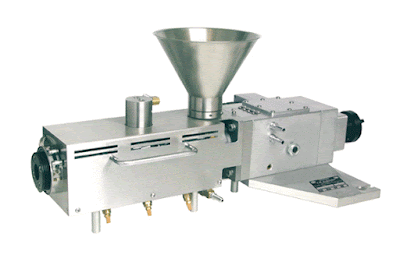
Our( http://ptfe-machinery.com/ ) has engineered its Single Screw Extruders with modular design concepts to meet market requirements. The result is built-in flexibility, lower cost, faster deliveries and ultimately, an exceptionally competitive value to our customers, from stand-alone extruders to complete systems. The single screw extruders handle applications such as sheet, custom profile, pipe, pelletizing, medical tubing, wire and cable.

A single-screw extruder is a press which pushes material through its barrel under conditions of high pressure and temperature. It can produce objects of different length with a cross-section corresponding to the outlet opening.

Single screw extrusion is one of the core operations in polymer processing and is also a key component in many other processing operations. The foremost goal of a single screw extrusion process is to build pressure in a polymer melt so that it can be extruded through a die or injected into a mold. Most machines are plasticating: they bring in solids in pellet or powder form and melt them as well as building pressure.

Applications

The extrusion process melts the raw material and then hardens it once shaped. It can be applied to ceramics, rubber, thermoplastic polymers, pasta and other food products.

Tag:Extrusion,Screw Extruders,Single Screw Extruders,Plastic,PTFE,Screw Extrusion,PTFE Screw Extruders

Sunday, March 12, 2017

Injection Molding Materials

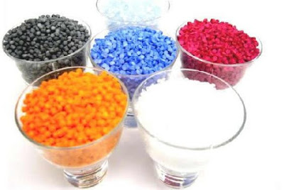
There are many types of materials that may be used in the injection molding process. Most polymers may be used, including all thermoplastics, some thermosets, and some elastomers. When these materials are used in the injection molding process, their raw form is usually small pellets or a fine powder. Also, colorants may be added in the process to control the color of the final part. The selection of a material for creating injection molded parts is not solely based upon the desired characteristics of the final part. While each material has different properties that will affect the strength and function of the final part, these properties also dictate the parameters used in processing these materials. Each material requires a different set of processing parameters in the injection molding process, including the injection temperature, injection pressure, mold temperature, ejection temperature, and cycle time.

Injection Molding Materials


Materials : Acetal,Acrylic,Acrylonitrile Butadiene Styrene,Cellulose Acetate,Polyamide 6 (Nylon),Polyamide 6/6 (Nylon),Polyamide 11+12 (Nylon),Polycarbonate,Polyester - Thermoplastic,Polyether Sulphone,Polyetheretherketone,Polyetherimide,Polyethylene - Low Density,Polyethylene - High Density,Polyphenylene Oxide,PTFE,Polyphenylene Sulphide,Polypropylene,Polystyrene - General purpose,Polystyrene - High impact,Polyvinyl Chloride - Plasticised,Polyvinyl Chloride - Rigid,Styrene Acrylonitrile,Thermoplastic Elastomer/Rubber...

Friday, March 10, 2017

Single Screw Extrusion - Plastics Technology


Single screw extrusion is one of the core operations in polymer processing and is also a key component in many other processing operations. The foremost goal of a single screw extrusion process is to build pressure in a polymer melt so that it can be extruded through a die or injected into a mold. Most machines are plasticating: they bring in solids in pellet or powder form and melt them as well as building pressure.

A single-screw extruder is a press which pushes material through its barrel under conditions of high pressure and temperature. It can produce objects of different length with a cross-section corresponding to the outlet opening.

Applications

The extrusion process melts the raw material and then hardens it once shaped. It can be applied to ceramics, rubber, thermoplastic polymers, pasta and other food products.

Technologies

These machines have a single screw turning within a cylinder, which is usually smooth. Raw material is fed into the barrel through a hopper and extruded into a die, which gives the material its final shape.

The barrel consists of three main zones: feed, compression and metering. The pressure increase within the extruder and movement of the material through the barrel are a function of screw geometry and the friction of the material against the screw and the barrel walls.

More Details:http://ptfe-machinery.com/single-screw-extruder/

Thursday, March 9, 2017

Materials Used - PTFE, PVDF Different

PFA is similar to PTFE in chemical resistance and temperature capabilities with continuous operating temperature ratings approaching 500 °F (260 °C). FEP has equal chemical resistance, but continuous operating temperature ratings are lower, on the order of 400 °F (204 °C). Both PFA and FEP, unlike PTFE, can be injection molded.

PVDF is similar to PTFE in that it is resistant to attack from a wide range of chemicals and is able to operate at higher temperatures than most plastics. The range of chemicals it can handle is not as broad as that of PTFE and its continuous operating temperature lower, but it can be injection molded and it is much stronger than PTFE within its operating temperature range. PVDF products can be susceptible to cracking if not properly stress-relieved.

PTFE, PVDF

Twin screw food extrusion

Twin screw extrusion technology was first used in 1956 as a technique for processing plastics and Clextral was a pioneer in that field. Clextral then became the first company to apply extrusion technology to food processing over 40 years ago.

Since then, it has continued to innovate and is today a recognized leader in new generation twin screw extruders for Food & Feed processing.

Twin screw food extrusion


Twin-screw extrusion processing versus conventional food processing

Sustainable: remarkable process-intensifying capability of twin-screw extrusion technology and associated processing lines allows determinant operational advantages to be achieved, such as: continuous HTST (High Temperature-Short Time) cooking, high productivity owing to reduced downtime and material losses, energy and water savings, reduced footprint.
Highly flexible: the same processing line is able to process various types of raw materials and mix formulations, and to produce a wide range of end products; whereas conventional cereal cooking processes (baking, hydrothermal cooking, etc.) are often limited to the production of low ranges of end-products with restricted possibilities to change operating parameters.
Fully automated, with high level of operating stability; hence leading to consistent product quality; whereas conventional processing lines require frequent adjustment of process parameters.
Fairly well suited to product innovation, with the possibility to target easily the four basic quality attributes of food products that are taste, flavour, texture and nutrition; product innovation may include upgrading of existing products as well as new products.
Economical and cost-effective, as they are characterized by reduced CAPEX and OPEX due to the remarkable process-intensifying capability of extrusion processing technology.

Tuesday, March 7, 2017

Typical Properties of Fluoropolymers(PTFE,FEP,ETFE,PVDF,PCTFE)

Properties of Fluoropolymers

PTFE Properties:
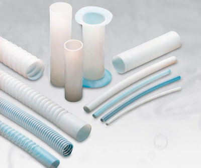
The Steel Industry and Chemical Processing Industry have been using fluoropolymer tubing products from materials like PTFE and hoses for many years for transferring highly caustic or corrosive chemicals. More and more, PTFE tubing is replacing carbon and other metal piping that deteriorates rapidly. Now and for the future, PTFE will continue to serve the industry in critical applications.

PTFE Thermal Qualities:
PTFE tubing can withstand temperatures up to 680 °F for limited periods of time.* Under cryogenic conditions, PTFE remains strong down to -320 °F.

*Above 500 °F, mechanical properties become a limiting factor

PTFE Electrical Qualities:
PTFE tubing has superb electrical properties, indicated by a low dielectric constant of 2.1 between -40 °F and 480 °F within a frequency range of 5 Hz to 10 GHz.

PTFE tubing is also an excellent insulator with surface resistivity of 3.6 X 10¹² ohms (even at 100% relative humidity).

Short time dielectric strengths range from 500 volts/mil (1 mil = 10-3 in) for thicknesses greater than 100 mils to 4000 volts/mil for very thin films.

FEP Properties:
Electrical FEP exhibits most of the properties of PTFE. However, because of its excellent electrical FEP properties, FEP tubing is a valuable and versatile electrical insulator.

Monday, March 6, 2017

Fluoropolymers (PTFE,PCTFE,PVF,PVDF) Properties

Fluoropolymers are produced from alkenes in which one or more hydrogen atoms have been replaced by fluorine. The most important members are polytetrafluoroethylene (PTFE), polychlorotrifluoroethylene (PCTFE), poly(vinyl fluoride) (PVF) and poly(vinylidene fluoride) (PVDF)

Due to the weak van der Waals forces, polyfluoroolefins have a very low coefficient of friction and very low surface tension and, due to the stability of the (multiple) carbon-fluorine bonds, excellent chemical resistance, which increases with the number of fluorine atoms in the repeat unit. They can be used both at high and very low temperatures and possess outstanding resistance to weathering (UV-resistance). Most fluoropolymers are also totally insoluble in most organic solvents and stable in concentrated acids and bases.
Fluoropolymers Properties


The largest-volume polyfluoroolefin is polytetrafluoroethylene (PTFE). This polymer has unique performance properties. It has outstanding thermal, electrical and chemical resistance and can be used both at very high (up to 530 K) and extremely low temperatures. Its coefficient of friction is among the lowest of all polymers (self-lubricating and non-stick). PTFE cannot be dissolved in any common solvent below its melting point. It is ideal for applications where broad chemical resistance, high durability, wide service temperature range, excellent dielectric properties, low friction, and non-stick are required. The properties of PTFE – high crystallinity, very high melting point (600 K), and very high melt viscosity – do not allow its processing by the usual process methods for plastics. Instead, similar to metal forming, the granular resins are processed by compression moulding at ambient temperature followed by sintering above the crystalline melting point.

Various copolymers of tetrafluoroethylene (PFA, FEP, ETFE) and other fluoropolymers with lower melting point and crystallinity were developed to overcome the lack of melt processability of PTFE. Among these, poly(vinylidene fluoride) (PVDF) is noteworthy. These resins are some of the easiest to process fluoropolymers. PVDF has high tensile and impact strength, and excellent resistance to tensile creep and fatigue. Like PTFE, it exhibits high thermal stability.

Sunday, March 5, 2017

Properties of PTFE and Some Other Materials Difference

PTFE (Polytetrafluoroethylene) Teflon ® The combination of chemical and physical properties of PTFE is a consequence of its true fluorocarbon structure. This unusual structure leads to a material which has an almost universal chemical inertness; complete insolubility in all known solvents below 300°C; excellent thermal stability; and unsurpassed electrical properties, including low dielectric loss, low dielectric constant and high dielectric strength. Furthermore, PTFE does not embrittle at very high or at very low temperatures.
Properties of PTFE


Corona Resistant PTFE is a corona resistant form of PTFE. It is a homogeneous insulation having essentially all of the properties of pure PTFE, but having approximately a thousand-fold longer high-voltage life. Corona Resistant PTFE is unique among high voltage insulations in its excellent resistance to electro-mechanical and chemical-mechanical stress cracking.

FEP (Fluorinated Ethylene Propylene) Teflon ®, life PTFE, has a fully fluorinated structure which leads to excellent chemical, thermal, and electrical properties. However, the high temperature limit for FEP is lower than PTFE, approximately 200°C instead of 260°C. FEP has good melt-flow characteristics which permit melt bonding to itself, to Kapton film, and to PTFE.

Polyurethane Extraordinary toughness and abrasion resistance are characteristics of polyurethane. As a result, cable jackets can be made considerably thinner than if more conventional jacketing materials were used. In addition, polyurethane has good low temperature performance, good weathering characteristics, and is resistant to oil, gasoline, and non-polar solvents.

PVC (Poly Vinyl Chloride) A good balance of properties: electrical, mechanical and thermal make PVC the choice material for cable jacketing applications where size and weight are not critical.

More:http://ptfe-machinery.com/properties-ptfe-insulating-materials/

Thursday, March 2, 2017

Fluoropolymer Rod/Pipe/Tubing Extrusion,Fluoropolymer Machine Show

What is a Fluoropolymer?

  •  A fluoropolymer is a polymer that contains molecules of carbon and fluorine. They are high-performance plastic materials used in harsh chemical and high-temperature environments, primarily where a critical performance specification must be met. They are used by defense-related industries and in automotive, aerospace, electronics and telecommunications.

Applications
  • Properties of fluoropolymers that have led to applications Minclude chemical resistance, thermal stability, cryogenic properties, low coefficient of friction, low surface energy, low dielectric constant, high volume and surface resistivity, and flame resistance.
  • Fluoropolymers are used as liners (process surface) because of their resistance to chemical attack. They provide durable, low maintenance, and economical alternatives to exotic metals for use at high temperatures without introducing impurities.
  • Electrical properties make fluoropolymers highly valuable in electronic and electrical applications as insulators, e.g., FEP in data communications.
  • Longer life;
  • Highly innovative;
  • Save time and money;
  • Tube OD Size range:20-600 mm;
  • Rod Dia Range Min – Max Dia:4mm – 500 mm;
  • Ram Machine ensures precision both in the pressing procedure and in the sinter zone;
  • Temperature controls are also provided.
  • Extruded fluoropolymer provides higher breakdown voltage because of lesser air voids in comparison to wrapped material.
  • Extruded fluoropolymers gives superior appearance and finishing.
  • Extruded fluoropolymer is having higher mechanical strength.
  • Extruded fluoropolymer can be used with tinned copper conductor also.